You need some software to get started. First you might need WinAVR. It's the
GCC compiler for AVR devices. Then I got the AVR Studio (Version 4 here) and
the latest service pack. Last a program called "PonyProg", because AVR Studio
cannot access the "high end" ISP cable I soldered.
Basic Programming
Well, I assume you know about { } and [ ] braces used in C / C++, so if you
don't get a book or read any other tutorial first. I read "teach yourself C in
21 days" which was rather good in my opinion.
The processor has pins and you can check if they're high (+5V at the pin) or
low (GND is at the pin). You can also program the chip to go high or low.
Setting the pin-state (Output):
That's rather easy: The Pins PDx are called "PORTD". PBx=PORTB and so on. First
you set the pin to be an output port. That's by writing:
DDRx |= (1 << p);
Where x is the port "name" and p is the port index. If you want PB5 to be your
output port, you write:
DDRB |= (1 << 5);
DDR means "data direction register" and a 0 bit indicates input, a 1 bit
indicates output. A mnemonic is "Data Dump Register", indicating 1 for dumping
(output) and 0 for non-duimping (input). You get acustomned to that very soon.
For accessing the whole port as output write:
DDRB = 0xff;
Now, if you want to set the pin's value, just write:
PORTx |= (1 << p);
and if you want to clear the bit (put it "low"), write:
PORTx &= ~(1 << p);
Reading Pin State (Input)
First, set the DDR to input for a pin:
DDRB &= ~(1 << 5);
That's just clearing the bit. Then activate the pull-up resistance for that
pin. You just write bit 1 for that PORT as if you were setting it "high".
PORTB |= (1 << 5);
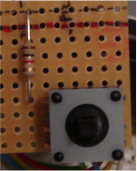
A "pullup resistance" is a resistance inside the chip, that keeps the pin
"high" if you don't do anything. You simply have to connect the port to GND in
order to "pull down" that resistance. This way you can access parts like
buttons and switches very easily. See below.
Then you can get the state of the pin with:
char IsBitHigh = PINx & (1 << p);
Right! Writing to a pin with "PORTx", reading from a pin with "PINx".
First Contact
If you soldered the thing above together, you can start writing you own
program.
Well, I hated starting with a flashing LED - I wanted to go big in the first
place. I was a fool. Take a short time to build this small tutorial LED
project. I give you hints how to make that all in just a few minutes. It's the
only way to see if your processor is working.
Launch the AVR Studio and build (hardware) the LED sample.
Copy/paste the code from below into a new project. Hit the "compile" button and
see the output window. It should not mention anything about errors.
The AVR studio created you a default/project_name.hex file. That's the program.
Now, connect you ISP cable to LPT1 and the circuit board, switch the power on,
open PonyProg and configure it for your first upload. Open Menu:
Setup/Interface Setup.
Select: Parallel, "Avr, ISP I/O", LPT1 and press "Probe" button. It should say:
Hokay!
Then select menu: Device/AVR micro/ATmega32 (or whatever you have). Finally
flash (=upload) the file using menu items:
File / Open (FLASH) Program File, select the .hex file
Command / Write Program (FLASH)
If everything goes smooth, your LED should start fading in/out now.
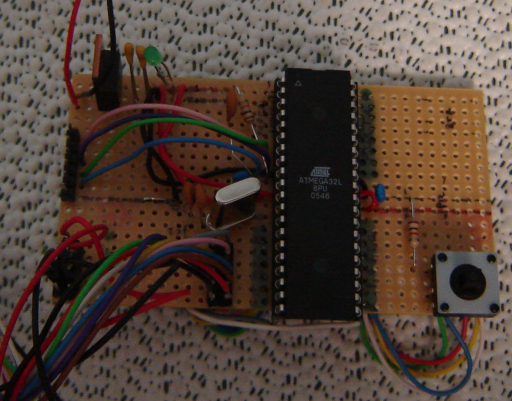
Extending the board
Next thing I did was soldering 5x2 pins on the board to make plugable
connections to the port. I used this pin-arrangement:
   +---+
  1|o o|0
  3|o o|2
  5|o o|4
  7|o o|6
VCC|o o|GND
   +---+


 Well, here's the assembly instruction for the board I built: First, I needed 5V
DC current. You can't get that at the groceries, so I took a cheap 6V adapter,
got a "7805 Positive Volt Regulator" and built this:
Well, here's the assembly instruction for the board I built: First, I needed 5V
DC current. You can't get that at the groceries, so I took a cheap 6V adapter,
got a "7805 Positive Volt Regulator" and built this: